CivilAxisCivilAxis
☕ Support🌐 Community

2×PFC 180×75×20 Back to Back - Section Properties

The 2×PFC 180×75×20 Back to Back is a parallel flange channel with a mass of 40.7 kg/m. It has a cross-sectional area of 51.8 cm², a second moment of area Iᵧ of 2740 cm⁴, a plastic modulus Wₚₗ,ᵧ of 352 cm³, tabulated by CivilAxis from BS EN 1993-1-1:2005 / BS 4-1:2005 (SCI P363 Blue Book).

Mass
40.7 kg/m
Area
51.8 cm²
Ask about capacity, buckling or detailing for 2×PFC 180×75×20 Back to Back.
🔍 Open the full Steel Catalogue📖 Design theory📐 Worked example
or pick a unit on any row
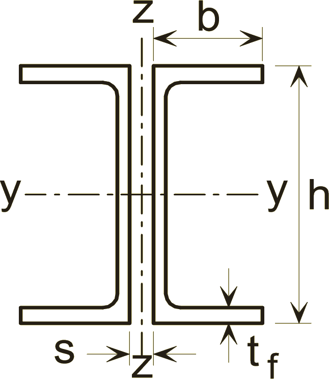
PFC Back to Back section profile showing the dimension symbols used for 2×PFC 180×75×20 Back to Back

Dimension symbols for PFC Back to Back sections. Not to scale.

2×PFC 180×75×20 Back to Back section properties to BS EN 1993-1-1:2005 / BS 4-1:2005.

Mass and area

Mass per metremass40.7
Cross-sectional areaA51.8

Bending about the major axis (y-y)

Area moment of inertia about y-axisIy2740
Elastic section modulus about y-axisWel,y304
Plastic section modulus about y-axisWpl,y352
Radius of gyration about y-axisiy7.27

Bending about the minor axis (z-z)

Area moment of inertia about z-axisIz2470
Elastic section modulus about z-axisWel,z185
Plastic section modulus about z-axisWpl,z264
Radius of gyration about z-axisiz3.68

Common questions about 2×PFC 180×75×20 Back to Back

2×PFC 180×75×20 Back to Back has a mass of 40.7 kg/m, tabulated to BS EN 1993-1-1:2005 / BS 4-1:2005. A 12 m length therefore weighs about 488 kg, which is the figure to use for a steel take-off or when checking a lift.

The plastic section modulus about the major axis, Wpl,y, is 352 cm³, and the elastic modulus Wel,y is 304 cm³. Wpl,y is what sets the moment capacity of a Class 1 or 2 section: M_pl,Rd = Wpl,y x f_y / gamma_M0, so at S355 with gamma_M0 = 1.0 this section reaches about 125 kNm before any stability check.

The second moment of area about the major axis, Iy, is 2,740 cm⁴, and about the minor axis Iz is 2,470 cm⁴. Iy is the value deflection depends on - for a simply supported beam under a uniform load, the midspan deflection is 5wL⁴/384EIy - so on spans where a deflection limit governs rather than strength, this is the number that decides the section.

iy is 7.27 cm about the major axis and iz is 3.68 cm about the minor axis. Column buckling is governed by the SMALLER value: the slenderness is lambda = L_cr / i, so with iz = 3.68 cm a 0.4 m effective length already gives lambda = 100. Minor-axis buckling almost always controls unless the weak axis is restrained.

Related PFC Back to Back sizes

2×PFC 230×75×26 Back to Back2×PFC 200×90×30 Back to Back2×PFC 200×75×23 Back to Back2×PFC 180×90×26 Back to Back2×PFC 150×90×24 Back to Back2×PFC 150×75×18 Back to Back2×PFC 125×65×15 Back to Back2×PFC 100×50×10 Back to Back

Learn more

📘 How to read a steel section table (UB, UC, IPE, HE)📘 Section modulus explained: elastic (Wel) vs plastic (Wpl)
All PFC Back to Back sizes
Two PFC - Back to Back
Full steel section tables
Every UB, UC, hollow, channel & angle section
Open the interactive tool
Search, compare & run EC3 capacity checks
Rate this
No ratings yet
Sign in to join the discussion.
Loading…