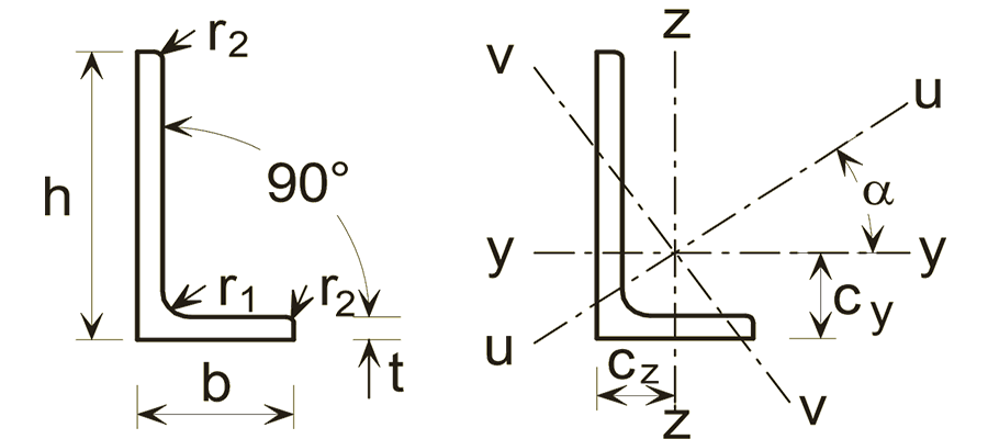
The UA 60×40×6 is a unequal angle with a mass of 4.46 kg/m, an overall depth of 60 mm and width of 40 mm. It has a cross-sectional area of 5.68 cm², a second moment of area Iᵧ of 20.1 cm⁴, an elastic modulus Wₑₗ,ᵧ of 5.03 cm³, tabulated by CivilAxis from BS EN 1993-1-1:2005 / BS EN 10056-1:1999 (SCI P363 Blue Book).
Mass
4.46 kg/m
Depth
60 mm
Width
40 mm
Area
5.68 cm²
Ask about capacity, buckling or detailing for UA 60×40×6.
UA 60×40×6 section properties to BS EN 1993-1-1:2005 / BS EN 10056-1:1999.
Geometry
Depth of section
h
60
Width of section
b
40
Web thickness
tw
6
Flange thickness
tf
6
Root fillet radius
r
6
Toe radius
r2
3
Mass and area
Mass per metre
mass
4.46
Cross-sectional area
A
5.68
Bending about the major axis (y-y)
Area moment of inertia about y-axis
Iy
20.1
Elastic section modulus about y-axis
Wel,y
5.03
Radius of gyration about y-axis
iy
1.88
Bending about the minor axis (z-z)
Area moment of inertia about z-axis
Iz
7.12
Elastic section modulus about z-axis
Wel,z
2.38
Radius of gyration about z-axis
iz
1.12
Principal axes
Area moment of inertia about u-u (major principal) axis
Iu
23.1
Area moment of inertia about v-v (minor principal) axis
Iv
4.16
Radius of gyration about u-u axis
iu
2.02
Radius of gyration about v-v axis
iv
0.855
Elastic section modulus about u-u axis
Wel,u
5.03
Elastic section modulus about v-v axis
Wel,v
2.38
Torsion and warping
Torsion constant (St Venant)
It
0.735
Detailing dimensions
Centroid distance from back of leg (y)
cy
2
Centroid distance from back of leg (z)
cz
1.01
Common questions about UA 60×40×6
UA 60×40×6 has a mass of 4.46 kg/m, tabulated to BS EN 1993-1-1:2005 / BS EN 10056-1:1999. A 12 m length therefore weighs about 54 kg, which is the figure to use for a steel take-off or when checking a lift.
UA 60×40×6 has a depth of 60 mm, a width of 40 mm, a web thickness of 6 mm, a flange thickness of 6 mm, with a cross-sectional area of 5.68 cm². These are the nominal dimensions from BS EN 1993-1-1:2005 / BS EN 10056-1:1999; rolling tolerances apply to the delivered section.
The elastic section modulus about the major axis, Wel,y, is 5.03 cm³. Angles are tabulated about their principal (u-u and v-v) axes rather than a plastic major-axis modulus, so the elastic value is the one to design from unless you are working from the principal-axis properties directly.
The second moment of area about the major axis, Iy, is 20.1 cm⁴, and about the minor axis Iz is 7.12 cm⁴. Iy is the value deflection depends on - for a simply supported beam under a uniform load, the midspan deflection is 5wL⁴/384EIy - so on spans where a deflection limit governs rather than strength, this is the number that decides the section.
iy is 1.88 cm about the major axis and iz is 1.12 cm about the minor axis. Column buckling is governed by the SMALLER value: the slenderness is lambda = L_cr / i, so with iz = 1.12 cm a 0.1 m effective length already gives lambda = 100. Minor-axis buckling almost always controls unless the weak axis is restrained.
The St Venant torsion constant It is 0.735 cm⁴. Closed sections carry torsion in a shear flow around the perimeter, which makes them far stiffer in torsion than an open section of the same weight and is usually why one is specified.