CivilAxisCivilAxis
☕ Support🌐 Community

CF RHS 60×40×3 - Section Properties

The CF RHS 60×40×3 is a rectangular hollow section with a mass of 4.25 kg/m, an overall depth of 60 mm and width of 40 mm and a wall thickness of 3 mm. It has a cross-sectional area of 5.41 cm², a second moment of area Iᵧ of 25.4 cm⁴, a plastic modulus Wₚₗ,ᵧ of 10.5 cm³, tabulated by CivilAxis from BS EN 10219-2:2006 (SCI P363 Blue Book).

Mass
4.25 kg/m
Depth
60 mm
Width
40 mm
Wall thickness
3 mm
Area
5.41 cm²
Ask about capacity, buckling or detailing for CF RHS 60×40×3.
🔍 Open the full Steel Catalogue📖 Design theory📐 Worked example
or pick a unit on any row
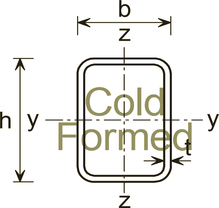
RHS Cold-formed section profile showing the dimension symbols used for CF RHS 60×40×3

Dimension symbols for RHS Cold-formed sections. Not to scale.

CF RHS 60×40×3 section properties to BS EN 10219-2:2006.

Geometry

Depth of sectionh60
Width of sectionb40
Wall thicknesst3

Mass and area

Mass per metremass4.25
Cross-sectional areaA5.41

Bending about the major axis (y-y)

Area moment of inertia about y-axisIy25.4
Elastic section modulus about y-axisWel,y8.46
Plastic section modulus about y-axisWpl,y10.5
Radius of gyration about y-axisiy2.17

Bending about the minor axis (z-z)

Area moment of inertia about z-axisIz13.4
Elastic section modulus about z-axisWel,z6.72
Plastic section modulus about z-axisWpl,z7.94
Radius of gyration about z-axisiz1.58

Torsion and warping

Torsion constant (St Venant)It29.3
Section modulus for torsionWt11.2

Classification and stability

Flange local-buckling ratiocf/tf10.3
Web local-buckling ratiocw/tw17

Surface area

Surface area per metreSA/m0.19
Surface area per tonneSA/t44.8m²/t

Is CF RHS 60×40×3 strong enough?

Simply supported beam, uniform load, major-axis bending - to EN 1993-1-1.

Passes - 62% utilised, deflection governs
Bending35%
1.3 / 3.7 kNm
Shear8%
5.3 / 66.5 kN
Deflection62%
1.7 / 2.8 mm

Class 1 section. ULS uses γQ = 1.5 on the load you enter; deflection uses the unfactored load against L/360. Lateral-torsional buckling is not included - the compression flange is assumed restrained.

Common questions about CF RHS 60×40×3

CF RHS 60×40×3 has a mass of 4.25 kg/m, tabulated to BS EN 10219-2:2006. A 12 m length therefore weighs about 51 kg, which is the figure to use for a steel take-off or when checking a lift.

CF RHS 60×40×3 has a depth of 60 mm, a width of 40 mm, a wall thickness of 3 mm, with a cross-sectional area of 5.41 cm². These are the nominal dimensions from BS EN 10219-2:2006; rolling tolerances apply to the delivered section.

The plastic section modulus about the major axis, Wpl,y, is 10.5 cm³, and the elastic modulus Wel,y is 8.46 cm³. Wpl,y is what sets the moment capacity of a Class 1 or 2 section: M_pl,Rd = Wpl,y x f_y / gamma_M0, so at S355 with gamma_M0 = 1.0 this section reaches about 4 kNm before any stability check.

The second moment of area about the major axis, Iy, is 25.4 cm⁴, and about the minor axis Iz is 13.4 cm⁴. Iy is the value deflection depends on - for a simply supported beam under a uniform load, the midspan deflection is 5wL⁴/384EIy - so on spans where a deflection limit governs rather than strength, this is the number that decides the section.

Its local-buckling ratios are cf/tf = 10.3 for the flange and cw/tw = 17 for the web. EN 1993-1-1 Table 5.2 compares these against limits scaled by epsilon = sqrt(235/f_y), so the class depends on the steel grade as well as the geometry - the same section can be Class 1 in S275 and Class 3 in S355. Use the Capacity tab on this page for the classification at a specific grade.

iy is 2.17 cm about the major axis and iz is 1.58 cm about the minor axis. Column buckling is governed by the SMALLER value: the slenderness is lambda = L_cr / i, so with iz = 1.58 cm a 0.2 m effective length already gives lambda = 100. Minor-axis buckling almost always controls unless the weak axis is restrained.

The St Venant torsion constant It is 29.3 cm⁴. Closed sections carry torsion in a shear flow around the perimeter, which makes them far stiffer in torsion than an open section of the same weight and is usually why one is specified.

Related RHS Cold-formed sizes

CF RHS 50×30×2.5CF RHS 50×30×3CF RHS 50×30×4CF RHS 60×40×2.5CF RHS 60×40×4CF RHS 60×40×5CF RHS 70×40×3CF RHS 70×40×4

Compare with other sections

Side-by-side properties against the closest equivalent in each catalogue.

vs RHS 60×40×3

Learn more

📘 How to read a steel section table (UB, UC, IPE, HE)📘 Section modulus explained: elastic (Wel) vs plastic (Wpl)📘 SHS vs RHS vs CHS: choosing a hollow steel section
All RHS Cold-formed sizes
Rectangular Hollow Sections - Cold-formed (BS EN 10219)
Full steel section tables
Every UB, UC, hollow, channel & angle section
Open the interactive tool
Search, compare & run EC3 capacity checks
Rate this
No ratings yet
Sign in to join the discussion.
Loading…