
Punching Shear Design of Flat Slabs to EC2
The EN 1992-1-1 clause 6.4 punching check step by step - the basic control perimeter at 2d, the beta factor for moment transfer, the concrete resistance vRd,c, the column-face crushing limit, and sizing shear studs and the outer perimeter - with a full worked example for an interior column.

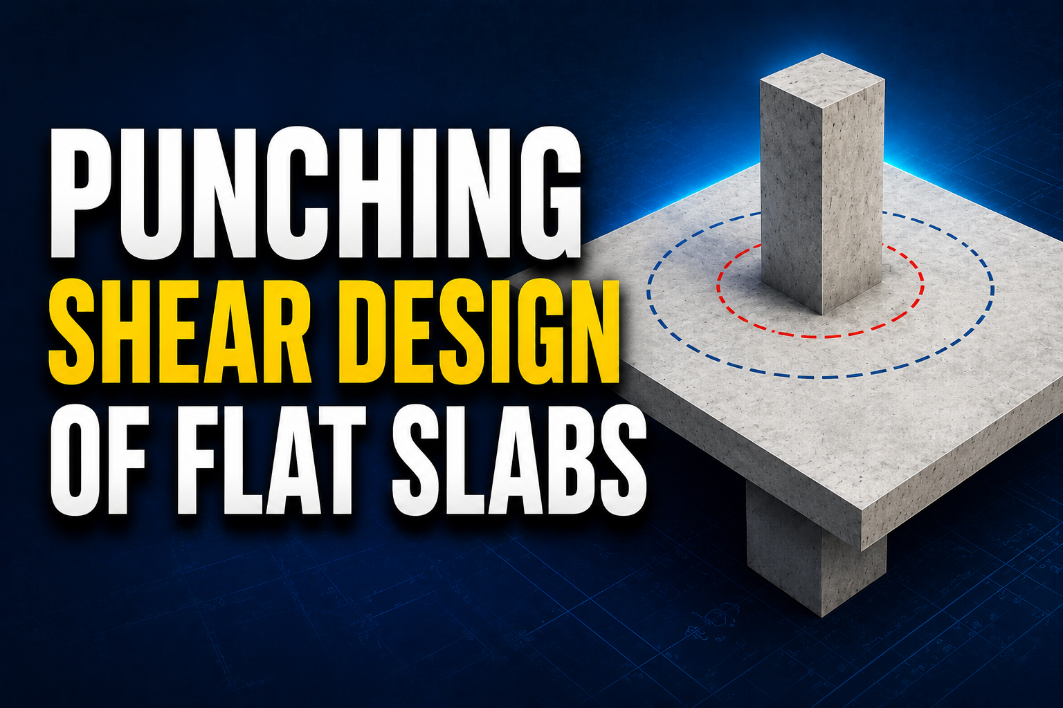
What this check does
A flat slab can fail by a cone of concrete punching out around a column - a brittle failure with almost no warning, and the reason several flat-slab collapses started at one connection. EN 1992-1-1 clause 6.4 checks that the design shear stress on a defined control perimeter does not exceed the punching resistance:
The check runs at two places: at the column face (concrete crushing) and at the basic control perimeter (the punching cone). If the slab alone is not enough, punching shear reinforcement (studs or links) makes up the difference.
The design shear stress
where:
- design shear force transferred to the column (N)
- the control perimeter being checked (mm)
- mean effective depth of the slab, (mm)
- factor for non-uniform shear from moment transfer (-)
The basic control perimeter is taken at a distance from the column face, with rounded corners. For a rectangular interior column :
accounts for the moment the slab transfers into the column, which concentrates shear on one side of the perimeter. Clause 6.4.3(6) gives the recommended simplified values for braced frames with roughly equal spans:
Column position | |
|---|---|
Interior | 1.15 |
Edge | 1.40 |
Corner | 1.50 |
Resistance without shear reinforcement
The punching resistance of the slab alone (clause 6.4.4) is the same empirical formula as beam shear:
where:
- calibration constant (recommended value)
- size effect factor ( in mm)
- mean bonded tension reinforcement ratio over a width each side of the column
- characteristic concrete cylinder strength (MPa)
- lower-bound resistance (MPa)
Note what helps: a thicker slab (but drops as grows), more tension steel over the column (cube-root effect, so doubling buys only 26%), and stronger concrete (also cube root). Punching is hard to fix with material strength alone.
The column-face crushing limit
Whatever reinforcement is added, the compression struts next to the column can crush. At the column perimeter (clause 6.4.5(3)):
where:
- column perimeter, for an interior rectangular column (mm)
- design concrete strength (MPa)
- strength reduction factor for shear-cracked concrete (-)
The values above are the EC2 recommended ones - always confirm and against your National Annex. If this check fails, no amount of studs saves the connection: increase the slab depth, the column size, or add a column head.
Punching shear reinforcement
Where at , shear reinforcement is required (clause 6.4.5):
where:
- area of one perimeter of shear reinforcement around the column (mm^2)
- radial spacing of the perimeters, (mm)
- effective design strength of the studs (MPa)
- angle of the reinforcement to the slab plane ( for vertical studs)
Note the concrete term is only once reinforcement is engaged, and the studs work at the reduced - a stud cannot anchor well enough in a thin slab to reach 435 MPa.
Reinforcement extends outward until the plain slab can carry the shear on an outer perimeter :
The outermost perimeter of studs must sit no further than inside (clause 6.4.5(4)); the first perimeter sits between and from the column face, radial spacing (clause 9.4.3).
Worked example - interior column
Slab: flat slab mm, mean effective depth mm. Column: interior, mm. Concrete: C30/37 ( MPa, ). Tension steel over the column: both ways. Load: kN, .
Perimeters:
Column-face check:
Stress at the basic control perimeter:
Plain-slab resistance:
MPa - the slab alone is not enough; shear reinforcement is required (utilisation 1.13 on the plain slab).
Stud sizing (vertical studs, mm, so ):
Eight 8 mm legs per perimeter give mm^2 mm^2
Outer perimeter:
For a square column , so the distance from the face is mm . With the last stud perimeter allowed inside , three perimeters at , and from the face (radial spacing ) cover the zone.
Result: the connection passes with 3 perimeters of 8 x 8 mm studs; the face check has ample margin (0.39 utilisation).
Key points
Punching is checked twice: crushing at the column face () and the cone at the basic perimeter $u_1 = $ face .
is never 1.0 in a real frame - 1.15 / 1.4 / 1.5 for interior / edge / corner columns is the simplified allowance for moment transfer.
grows only with the cube root of steel ratio and concrete strength - depth and column size are the real levers, and at the face caps everything.
Studs work at , not full yield, and the concrete term drops to - do not size them by hand-waving.
Detailing rules (first perimeter -, spacing , last perimeter inside ) are part of the check, not an afterthought.
References
- 1. EN 1992-1-1:2004 - Design of concrete structures, clause 6.4 (punching shear) and 9.4.3 (detailing)
- 2. The Concrete Centre - Concise Eurocode 2, chapter on punching shear (procedure basis)