
Steel Column Buckling Design to Eurocode 3

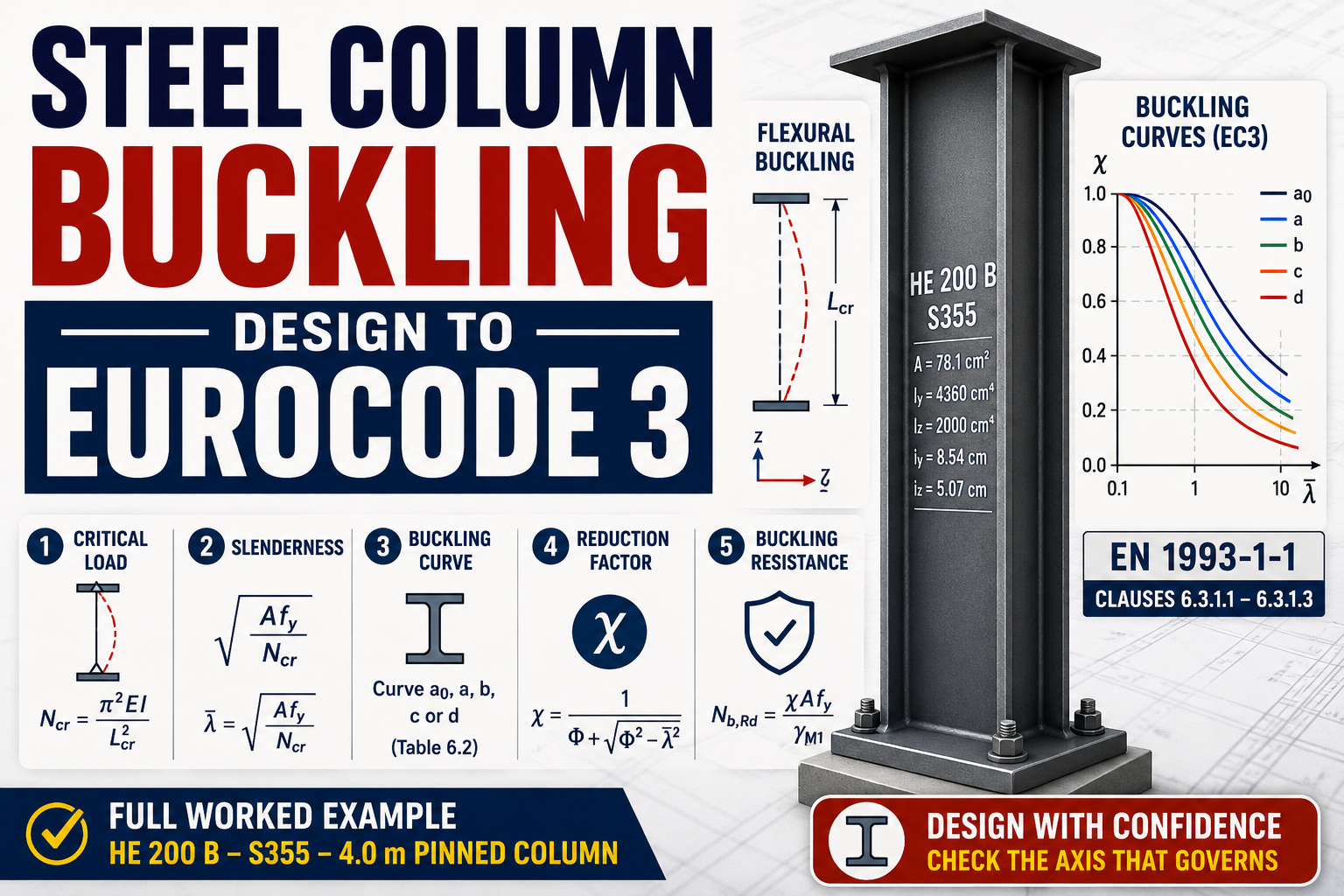
What this check does
A compression member almost never fails by squashing at - it bows sideways first. EN 1993-1-1 clause 6.3.1 checks that the design axial force does not exceed the buckling resistance:
where:
- design axial compression (N)
- reduction factor for the governing buckling mode (-)
- gross area, for Class 1-3 sections (mm^2)
- yield strength (MPa)
- partial factor for member buckling (recommended value)
Everything in this check funnels into : how slender the column is, and how imperfect its shape and residual stresses are.
Step 1 - critical load and buckling length
The elastic critical (Euler) load about each axis:
where:
MPa - modulus of elasticity
- second moment of area about the buckling axis (mm^4)
- buckling length about that axis (mm)
reflects the end restraints: pinned-pinned, fixed-pinned, fixed-fixed in theory ( and are the usual practical values), for a cantilever. In braced frames columns are commonly taken as ; a column can (and often does) have different buckling lengths about each axis - for example when side rails restrain the weak axis mid-height.
Step 2 - non-dimensional slenderness
where:
- non-dimensional slenderness (-)
- radius of gyration about the buckling axis (mm)
- the slenderness at which the Euler load equals the squash load
marks the crossover: below it yielding dominates, above it elastic buckling does. Note that raising the steel grade increases - a slender column gains almost nothing from S355 over S275, because contains , not .
Step 3 - pick the buckling curve
Real columns carry residual rolling stresses and initial bow, so they fail below the Euler load. EC3 calibrates this with five curves (a0, a, b, c, d) via the imperfection factor :
Curve | a0 | a | b | c | d |
|---|---|---|---|---|---|
0.13 | 0.21 | 0.34 | 0.49 | 0.76 |
For rolled I and H sections with mm (Table 6.2):
Shape | Axis y-y | Axis z-z |
|---|---|---|
(tall, IPE-like) | a | b |
(square, HE-like) | b | c |
Stocky wide-flange columns get the worse curves - their thick flanges carry the highest residual stresses. (S460 upgrades to a0/a; see Table 6.2.)
Step 4 - reduction factor
For (or ) buckling may be ignored and . Both axes are checked; **the smaller governs**. For a doubly symmetric section that is usually the z-z (weak) axis, unless intermediate restraints shorten it.
Worked example - HE 200 B, S355, 4.0 m pinned column
Column: m, pinned both ends about both axes ( m), kN. Section (CivilAxis steel catalogue): HE 200 B - cm^2, cm^4, cm, cm, , mm. Steel: S355 ().
Classification (pure compression): flange ; web - Class 1, so the full area counts.
Critical load, weak axis:
Slenderness:
(Cross-check via radii: ; , .)
Curve: , mm - z-z uses curve c, (y-y uses curve b).
Reduction factor, z-z:
(The same steps about y-y give - the weak axis clearly governs.)
Buckling resistance:
Result: kN - the column passes at 0.83 utilisation. Buckling has cut the squash capacity ( kN) nearly in half - that missing 48% is what the slenderness and curve c imperfections cost.
Key points
The check is - all the physics lives in , built from , and the imperfection factor .
Buckling lengths follow the restraints, per axis - a mid-height rail on the weak axis can flip which axis governs.
Square H-columns take curves b/c (heavier residual stresses); tall I-shapes take a/b.
Higher steel grade barely helps a slender column: depends on and geometry, not .
At , expect to lose roughly 40-50% of the squash load on curve c - if the utilisation looks too good, check which axis (and which curve) was actually used.