
 CivilAxis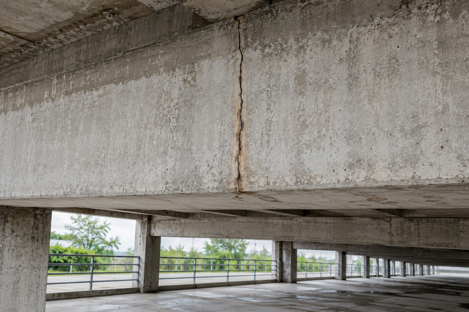
A reinforced concrete beam is designed to crack. That is not a failure of the design, it is the design. Concrete is roughly ten times weaker in tension than in compression, so the moment a beam picks up any real load, the tension face cracks and the reinforcement takes over. A beam that has not cracked is a beam that is not working yet.
So when Eurocode 2 sets a crack width limit of 0.3 mm for ordinary members, it is not trying to prevent cracking. It is limiting how wide the cracks get. The question worth asking is why 0.3, and what goes wrong at 0.4.
It is a corrosion limit, not a leak limit and not an aesthetic one
The reinforcement in a concrete member is protected by chemistry, not by the concrete's physical barrier. Fresh concrete is strongly alkaline, around pH 13, and at that alkalinity steel forms a passive oxide film that will not corrode. Destroy the alkalinity and the film goes with it.
Two things destroy it. Carbon dioxide from the air reacts with the concrete and drops the pH, a front that advances slowly inward from the surface. Chlorides, from de-icing salt or seawater, break the passive film directly at much lower concentrations. A crack is a shortcut for both: it lets the aggressive front skip the cover it would otherwise have to diffuse through.
That framing explains features of the code that otherwise look arbitrary. The limit is relaxed to 0.4 mm for members in benign, dry internal conditions, where there is little to drive corrosion. It is tightened for chloride exposure. And for water-retaining structures, EN 1992-3 leaves the durability framework entirely and works to tightness classes, because there the concern is leakage rather than corrosion, and the acceptable width is much smaller.
The limit is also not a precision number. Research on cracked members has repeatedly found the correlation between surface crack width and actual corrosion rate to be weak, because what governs corrosion is the environment at the bar and the quality of the cover concrete, not the width of the line you can see. The 0.3 mm figure is a durable, calibrated convention that keeps designs in a zone that has performed acceptably. It should not be treated as a cliff edge where 0.29 is safe and 0.31 is not.
What the formula is actually made of
Two terms, and each one is doing something physical.
is the maximum crack spacing. Cracks cannot form arbitrarily close together, because after a crack forms it takes a certain bond length before the concrete has picked up enough stress from the bar to crack again. Longer spacing means fewer cracks sharing the same total extension, so each one is wider.
is the difference between the average strain in the steel and the average strain in the concrete between cracks. That difference, integrated over the crack spacing, is the crack width. The concrete between cracks is still carrying tension through bond, an effect called tension stiffening, and it is what stops the crack being as wide as a naive calculation would suggest.
The crack spacing term is where the surprise lives:
with , for ribbed bars, for bending and . The first term is proportional to the cover. Which means, straightforwardly: more cover, wider cracks.
The paradox, quantified
Take a 300 by 600 beam, effective depth 550 mm, C30/37 concrete, 3 No. 20 mm bars, under a quasi-permanent moment of 100 kN.m.
The cracked neutral axis comes out at 126.9 mm, giving a lever arm of 507.7 mm and a steel stress of 209.1 MPa. The effective tension area is 125 mm deep, so . The strain difference works out at , comfortably above the floor.
With 35 mm cover:
Now the same beam, same bars, same load, but with 50 mm cover because the exposure class was upgraded:
Fifteen millimetres of extra cover, added specifically to protect the reinforcement, widened the calculated surface crack by 20 percent. Both still pass, but the direction is the opposite of what intuition says.
Why that is not actually a contradiction
The resolution is that the crack is not a constant width through the depth of the cover. It is narrow at the bar and opens out towards the surface, roughly in proportion to the distance from the steel. The formula predicts the width at the surface, because that is what is measurable and what an inspector will record. But the width that matters for corrosion is the one at the bar, and that has not got worse. The extra cover both lengthens the diffusion path and keeps the crack tight where the steel is.
So the two effects genuinely pull in opposite directions on the number, and the code has been calibrated knowing that. It is still worth understanding, because it tells you what to do when a crack check fails.
What to change when the check fails
The instinct is to add steel. It works, but it is usually the least efficient of the available moves, because falls only in proportion to the added area while the cost rises the same way.
Look at the formula again and the cheaper lever is obvious. The bar diameter appears in the numerator of the spacing term, and in the denominator depends on the steel area. Replacing a few large bars with more smaller bars of the same total area reduces the crack width without adding a kilogram of steel. More bars means more bond surface, closer crack spacing, and narrower individual cracks. This is why EC2 offers the maximum-bar-diameter and maximum-bar-spacing tables as a deemed-to-satisfy route: they encode exactly this trade.
The order to try things in:
Redistribute the bars: same area, smaller diameter, more of them.
Check whether the quasi-permanent combination was actually used. Using the characteristic combination by mistake inflates and fails members that are fine.
Reconsider the exposure class before accepting a cover increase you do not need.
Only then add steel.
Takeaways
Cracking is designed for, not designed out. A crack limit controls width, not existence.
The limit is a corrosion limit. Leakage is EN 1992-3, and appearance is not the driver at all.
0.3 mm is a calibrated convention, not a precise threshold. Treat 0.28 and 0.32 as the same answer.
Crack width is crack spacing multiplied by the strain difference. Both terms are physical.
More cover gives a wider surface crack but not a wider crack at the bar. In the example, 35 to 50 mm cover moved the result from 0.20 to 0.24 mm.
To pass a failed check, change bar diameter before adding bar area.
Confirm you are using the quasi-permanent combination before doing anything else.
#ec2 #eurocode #concrete #durability #crackwidth #serviceability