
Beam Shear to EC2: the Variable Strut Inclination Method
Eurocode 2 lets you choose the angle of the concrete strut, and that one choice changes the link quantity by a factor of 2.5. This article explains what the truss model assumes, why the strut angle is bounded between 21.8 and 45 degrees, how the concrete crushing limit decides which end of that range you can use, and works a full 300 by 600 beam through the check by hand.

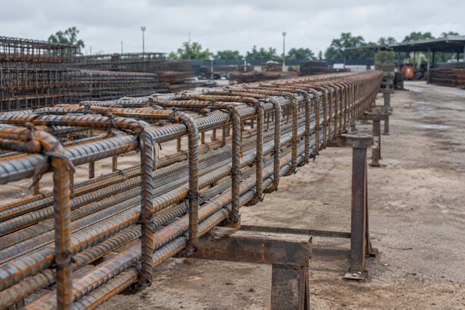
What this check does
A beam fails in shear in one of two ways, and Eurocode 2 makes you prove that neither happens. Either the stirrups yield and a diagonal crack opens until the section comes apart, or the concrete between two diagonal cracks is crushed by the compression running along it. The first is a ductile, visible failure. The second is sudden. The check is therefore two inequalities, not one:
where:
- design shear force at the section considered (kN)
- resistance governed by yielding of the shear reinforcement (kN)
- resistance governed by crushing of the concrete struts (kN)
The subtlety that catches people out is that these two are not independent. They are both functions of the same strut angle, and moving that angle to help one hurts the other.
First: do you need links at all?
Before the truss model, EC2 §6.2.2 gives the resistance of a member with no shear reinforcement:
with a floor value that applies when the longitudinal steel ratio is low:
where:
- equals , so 0.12 for the recommended
- size factor, , with in mm
- tension steel ratio
- characteristic cylinder strength (MPa)
- minimum web width (mm)
- effective depth (mm)
The size factor is the part worth understanding. It is capped at 2.0, which is reached at mm, and it falls towards 1.0 as the member gets deeper. A deep beam has less shear resistance per unit area than a shallow one with the same materials and the same steel ratio. This is the size effect: a bigger member has wider cracks at the same strain, wider cracks transfer less aggregate interlock, and the concrete contribution drops. It is a real, measured effect, not a safety fudge.
If , no calculated shear reinforcement is needed, though minimum links still apply to beams.
The truss model, and why the angle is free
Once links are required, the concrete term is dropped entirely. This surprises engineers coming from older codes: EC2 does not add to the link resistance. The truss carries all of it.
The model is a plane truss. The tension chord is the longitudinal steel, the compression chord is the flexural compression zone, the vertical ties are the links, and the diagonals are concrete struts running at an angle to the beam axis. Resolving the vertical equilibrium of the truss gives:
where:
- cross-sectional area of the shear reinforcement in one set of links (mm²)
- spacing of the links along the member (mm)
- inner lever arm, taken as for a member without axial force (mm)
- design yield strength of the shear reinforcement (MPa)
- angle between the concrete strut and the beam axis
Read that equation as a statement about geometry. A diagonal crack at angle crosses a horizontal distance , so it is crossed by links. Flatten the strut, cross more links, carry more shear with the same reinforcement. That is the whole idea, and it is why the angle is worth money.
The crushing limit is what stops you
If flattening the strut were free, everyone would use the flattest angle allowed. It is not free, because the same flattening increases the force in the concrete diagonal:
where:
- coefficient for the state of stress in the compression chord, 1.0 for non-prestressed members
- strength reduction factor for concrete cracked in shear,
- design compressive strength,
The denominator is the key. It is minimised at , where it equals 2, and it grows as the strut flattens: at it is 2.9. So the crushing resistance is highest at 45 degrees and lowest at the flattest angle, while the link resistance does exactly the opposite. The two curves cross, and design sits wherever the section allows.
EC2 bounds the choice at:
that is, . The upper bound on is not a physical limit so much as a limit on how much redistribution the code will trust: at very flat angles the crack widths and the strain demand on the links become larger than the model's assumptions support.
The practical design sequence follows directly. Try first, because it minimises the links. Check at that angle. If it passes, you are done and you have the cheapest solution. If it fails, steepen the strut until , and design the links for that steeper angle.
The price paid by the tension chord
The truss diagonals push horizontally as well as vertically, and that horizontal component has to be equilibrated by the tension chord. So shear increases the force in the longitudinal steel:
where:
- additional tensile force in the longitudinal reinforcement (kN)
- angle of the shear reinforcement to the beam axis, 90 degrees for vertical links so
At this is , which is not small. It is the reason for the shift rule in §9.2.1.3 and the reason bottom bars must run into supports and be properly anchored rather than curtailed where the bending moment diagram says they could be. A beam that is fine for bending and fine for shear can still fail because the bottom steel was curtailed as if the shear did not exist.
Detailing limits that override the arithmetic
Requirement | Expression | Clause |
|---|---|---|
Minimum ratio | §9.2.2(5) | |
Maximum longitudinal spacing | §9.2.2(6) | |
Maximum transverse spacing | mm | §9.2.2(8) |
Strut angle range | §6.2.3(2) |
The minimum ratio exists so that when a diagonal crack does form, the links can carry what the uncracked concrete was carrying, rather than snapping and turning a crack into a failure. It is a ductility requirement, not a strength one.
Worked example
Section: mm, mm, mm. Materials: C30/37, B500 links, , , so MPa and MPa. Tension steel: 3 No. 25 mm, mm². Design shear: kN.
Step 1, the concrete-only resistance:
The floor value gives MPa, so kN, which does not govern. With kN against kN, designed links are required and the concrete term is now discarded.
Step 2, try the flattest strut, :
kN, so the section is nowhere near its crushing limit and the flattest strut is available. Use it.
Step 3, size the links:
Two-leg 10 mm links give mm², so mm. Provide 10 mm links at 225 mm centres.
Step 4, verify what was provided:
Result: kN against kN, a utilisation of 0.93, with crushing at 540.7 kN well clear. Provided against a minimum of 0.263, and 225 mm spacing against a maximum of 412.5 mm. The section passes on all four counts. Note the additional chord force this creates: kN, which the bottom steel and its anchorage must carry.
Had the beam been narrower, say mm, at would fall to 360.5 kN. Still above 350 kN, but the margin is thin enough that a small increase in load would force a steeper strut and roughly a third more link steel. That cliff edge is worth knowing about before the loads are finalised.
Key points
The two failure modes are checked separately and both depend on the same strut angle, in opposite directions.
Once links are required, is discarded. The truss carries the whole shear.
Start at for the lightest links, then steepen only if the crushing check fails.
is governed by web width. A narrow web, not a weak link, is what forces a steeper strut.
Flattening the strut adds to the tension chord. Anchor the bottom steel for it.
The size factor means deep beams get less concrete shear resistance, which is physics, not conservatism.
#eurocode #ec2 #concrete #shear #beamdesign
References
- EN 1992-1-1:2004 - Design of concrete structures - Part 1-1 - §6.2.1 to §6.2.3
- EN 1992-1-1:2004 - §9.2.2 - Detailing of shear reinforcement in beams