
Circular Columns to TCVN 5574: Axial Load and Bending
A circular column has no fixed compression block and no two bars at the same depth, so the rectangular formulas do not transfer. This article explains why circular sections need strain-compatibility integration over a circular segment, how the N-M interaction diagram is built and read, and works a 600 mm column with 12 D25 bars all the way through against a verified engine.

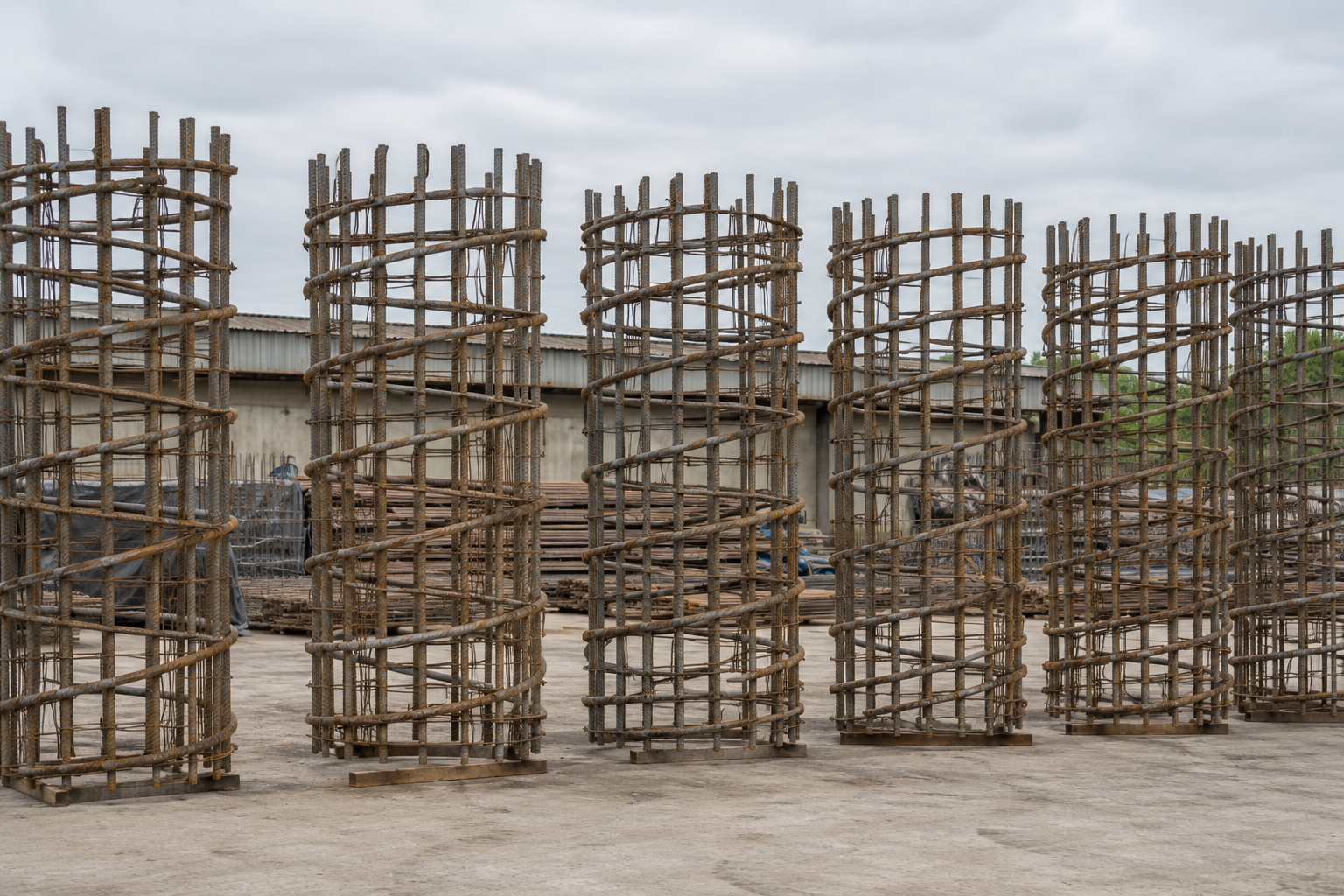
Why a circular column is a different problem
For a rectangular section, the ultimate limit state has a comfortable shortcut. The compression zone is a rectangle of width and depth , its area is , and its centroid sits at . Two layers of steel sit at two known depths. The equilibrium equations close in a few lines of algebra.
A circular column gives you none of that. The compression zone is a circular segment, whose area and centroid both change nonlinearly with the neutral axis depth. The bars sit on a ring, so every bar is at a different distance from the extreme compression fibre, and as the section rotates about a different axis the whole pattern changes. There is no equivalent of "tension steel" and "compression steel" as two lumps, because the bars grade continuously from fully yielded in compression to fully yielded in tension.
So the check is done by integration, not by formula:
where:
- concrete stress at a point, from the assumed stress block (MPa)
- stress in bar , from its strain and the steel law (MPa)
- area of bar (mm²)
- distance of bar from the section centroid (mm)
Both integrals are taken over the compressed segment only. The concrete term has a closed form worth knowing: for a chord depth measured from the extreme fibre, with central half-angle , the segment area is . When the neutral axis sits exactly at the centroid, this reduces to the half-circle with first moment , and those two identities are what the engine's geometry is verified against.
The strain plane and the material laws
Everything follows from one assumption: plane sections remain plane. A single straight strain line across the section fixes the strain in every fibre and every bar. Fix the extreme compression strain at the concrete limit and vary the neutral axis depth, and you sweep out every possible failure state of the section.
TCVN 5574 uses design strengths directly rather than characteristic values divided by partial factors at the point of use:
Quantity | Symbol | B30 / CB500-V |
|---|---|---|
Concrete compressive design strength | 17.0 MPa | |
Steel tensile design strength | 435 MPa | |
Steel compressive design strength | 435 MPa | |
Steel elastic modulus | 200 000 MPa |
Note that for CB500-V. This is not automatic across all grades, and it matters: it is what makes the interaction diagram close to symmetric in its steel contribution.
The interaction diagram, and how to read it
Sweeping the neutral axis produces a curve in the - plane. Four points on it carry most of the meaning:
Squash load. Neutral axis at infinity, whole section in uniform compression, no moment. , using the gross concrete area.
Balanced point. The extreme concrete fibre reaches its crushing strain at the same instant the most-tensioned bar reaches yield. This is where the moment capacity is at its maximum, which is the single most counter-intuitive feature of the diagram.
Pure bending. Zero axial load, the ordinary flexural capacity .
Pure tension. All concrete cracked, every bar yielded in tension. .
The consequence of the balanced point is worth stating plainly: adding axial compression to a lightly loaded column increases its moment capacity. Compression closes the cracks and enlarges the concrete compression zone, so the internal lever arm grows. This continues up to the balanced point, after which more axial load starts to consume the compression zone and the moment capacity falls away steeply towards the squash point. A column is at its strongest in bending somewhere in the middle of its axial range, not at the bottom.
Eccentricity: what the column is actually asked to carry
The demand side is not simply the applied moment. TCVN 5574 builds it from eccentricities:
where:
- the load eccentricity implied by the applied actions (mm)
- accidental eccentricity covering construction tolerance and unintended out-of-straightness (mm)
- the design eccentricity actually used (mm)
- effective length of the member (mm)
- section depth, the diameter for a circular column (mm)
The design moment is then , with a slenderness amplifier for second-order effects. For a stocky column is 1.0 and the amplification vanishes; for a slender one it can dominate the design.
The accidental eccentricity is not a formality. For a 600 mm column it is 20 mm, and a column carrying a genuinely concentric 2000 kN would still be designed for kN.m. There is no such thing as a pure axial column in this code, which is correct: there is no such thing as one on site either.
Worked example
Every value below is the output of the verified CivilAxis TCVN circular engine for this exact input set.
Section: mm, cover 40 mm, 10 mm links, 12 D25 bars on the ring. Materials: B30 concrete, CB500-V steel, so MPa, MPa, MPa. Actions: kN, kN.m, effective length mm.
Total steel area:
The two ends of the interaction diagram:
The moment capacities along the curve:
Read those three numbers together, because they make the point of the whole article. At zero axial load the column carries 507.6 kN.m. At 2000 kN of compression it carries 650.7 kN.m, which is 28 percent more. The applied 2000 kN sits essentially at the balanced point, the strongest place on the curve.
The demand:
The load eccentricity governs comfortably, and with the column is stocky enough that .
Result: utilisation . The section is at 46 percent of its capacity, with a large reserve. Note what would happen if the axial load were removed while the moment stayed: the capacity would drop to 507.6 kN.m and the utilisation would rise to 0.59. Losing compression makes this column weaker, not safer, and load cases that shed axial load while keeping moment (uplift under wind, for instance) deserve their own check rather than being assumed benign.
Shear, by equivalent rectangle
TCVN handles circular shear by converting the section to an equivalent rectangle rather than integrating again. The engine takes and computes an effective depth to the centroid of the tension-side bars. For this section:
With 2-leg 10 mm links at 200 mm centres and kN applied:
The effective depth mm is larger than the radius, which is the check worth remembering: the tension bars sit spread around the far half of the ring, so their centroid falls beyond the centre line.
Serviceability
The cracking moment for this section is:
But cracking is not decided by moment alone. Under kN with a service moment of 50 kN.m, the engine reports the section uncracked with : the axial compression keeps the whole section closed. Reverse the balance to kN with a service moment of 400 kN.m and the same section cracks, with mm and a deflection of 3.4 mm over the 4 m length.
That contrast is the serviceability version of the same lesson as the interaction diagram. The axial load is not a passenger. It changes whether the section cracks at all.
Key points
Circular sections are solved by integration over a circular segment, not by a rectangular stress block.
Every bar is at a different depth, so there is no "tension steel" and "compression steel" pair.
The moment capacity peaks at the balanced point. Compression makes a lightly loaded column stronger in bending, up to a point.
For this 600 mm column, 2000 kN of compression raised the moment capacity from 507.6 to 650.7 kN.m, a 28 percent gain.
Accidental eccentricity means no column is ever designed as purely axial.
Load cases that remove axial load while keeping moment can be more critical than the fully loaded case.
Shear uses an equivalent rectangle with ; the effective depth lands beyond the centre line.
#tcvn #tcvn5574 #concrete #column #interactiondiagram
References
- TCVN 5574:2018 - Thiết kế kết cấu bê tông và bê tông cốt thép - muc 8.1
- TCVN 5574:2018 - muc 8.1.3 - Cấu kiện chịu nén lệch tâm
- CivilAxis verified engine - scripts/test-tcvn-circ.mjs (19/19)