
Lateral Earth Pressure: Rankine, Coulomb and EN 1997
Earth pressure is not a property of the soil alone; it depends on which way the wall moves and how far. This article explains the at-rest, active and passive states and the very different movements each needs, derives the Rankine and Coulomb coefficients, and works a 5 m wall with and without a water table to show why groundwater, not soil, is what usually overturns a retaining wall.

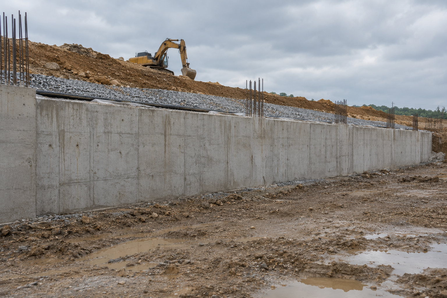
Earth pressure is a function of movement
The single most important idea in retaining wall design is that the soil does not push with a fixed force. What it pushes with depends on what the wall does. Build a wall that cannot move at all and the soil stays in the state it was deposited in. Let the wall move away from the soil and the pressure falls, because the soil mobilises its own shear strength to hold itself up. Push the wall into the soil and the pressure rises steeply, because now the soil's shear strength is working against you.
Three states, then:
State | Wall movement | Coefficient | Relative magnitude |
|---|---|---|---|
At rest | None | Intermediate | |
Active | Away from the soil | Lowest | |
Passive | Into the soil | Highest, by a large margin |
For a normally consolidated soil the at-rest coefficient is estimated by Jaky's expression:
where:
- coefficient of earth pressure at rest
- effective angle of shearing resistance of the soil (degrees)
How much movement, and why it matters more than the coefficients
The coefficients are only half the story. The other half is how far the wall has to move to reach each state, and the two answers are not remotely similar.
The active state is reached almost immediately. For a granular soil, a rotation or translation of roughly 0.001 to 0.005 times the wall height is enough to drop the pressure from at-rest to fully active. On a 5 m wall that is 5 to 25 mm, which any real wall will accommodate through construction tolerance and normal flexure without anyone noticing.
The passive state is completely different. Mobilising full passive resistance takes something like 0.02 to 0.06 times the wall height, so 100 to 300 mm on that same 5 m wall. That is a visible, serviceability-destroying movement.
This asymmetry has a direct design consequence that is worth stating bluntly: you may generally assume the active pressure is fully developed, but you may not assume the full passive resistance is available. Passive resistance in front of a wall is routinely reduced, or discounted entirely for the upper zone that might be excavated for a service trench at some future date. A design that balances active against full passive is a design that only works after the wall has already moved too far to be acceptable.
Rankine: the simple case, and its assumptions
Rankine's solution comes from considering the stress state in the soil at the point of failure. For a smooth vertical wall retaining a horizontal, cohesionless backfill:
where:
- active earth pressure coefficient
- passive earth pressure coefficient
Note the reciprocal relationship, , which is a useful arithmetic check on any pair of values you compute.
The horizontal effective pressure at depth is then:
where:
- horizontal effective stress (kPa)
- vertical effective stress (kPa)
- bulk unit weight of the soil (kN/m³)
- pore water pressure at that depth (kPa)
Rankine's assumptions are restrictive and worth listing, because each one is a case where the answer is wrong if you ignore it: the wall is vertical, the wall is smooth (no friction between wall and soil), the backfill surface is horizontal, and the soil is homogeneous. Real walls violate at least one of these most of the time.
Coulomb: wall friction, and why it helps
Coulomb's approach is different in kind. Instead of a stress state, it considers a wedge of soil sliding on a plane and finds the wedge geometry that gives the worst force on the wall. Its value is that it accommodates what Rankine cannot: friction on the back of the wall, a sloping backfill, and a wall face that is not vertical.
where:
- angle of friction between the wall and the soil (degrees)
- inclination of the back of the wall from vertical (degrees)
- inclination of the backfill surface from horizontal (degrees)
Set , and and this collapses back to the Rankine value, which is the sanity check to run if you ever implement it.
Wall friction reduces the active pressure, sometimes appreciably, because part of the wedge's weight is carried in shear on the wall face rather than pushing horizontally. It is tempting to claim it. Be careful: depends on the wall material and its roughness, and it can be destroyed by construction practice, by a smooth membrane behind the wall, or by the wall settling relative to the soil. Claiming a generous on a wall that may later settle is claiming a benefit that can disappear.
A known limitation: Coulomb's method is unconservative for the passive case at high wall friction, because the real failure surface curves and the planar wedge assumption overestimates the resistance. Where passive resistance matters and is significant, use a method based on a curved failure surface instead.
Water is what actually fails retaining walls
Here is the error that does the most damage in practice. The earth pressure coefficient applies to the effective stress. It does not apply to water pressure. Water has no shear strength, so it pushes with its full hydrostatic pressure in every direction:
where:
- pore water pressure (kPa)
- unit weight of water, 9.81 kN/m³
- depth below the water table (m)
Applying to the water pressure understates the load badly, and it is an easy mistake to make when the calculation is set up as one pressure diagram. The worked example below quantifies it.
This is also why drainage behind a wall is a structural measure rather than a durability nicety. A drained wall carries the active pressure of the soil. The same wall with a blocked drain carries the active pressure of the submerged soil plus full hydrostatic water pressure, which as shown below is a large increase. Retaining walls fail after heavy rain far more often than they fail under their design soil load.
Cohesion and the tension crack
For a cohesive soil, the active pressure gains a negative term:
where:
- effective cohesion of the soil (kPa)
Near the surface this goes negative, implying the soil pulls on the wall. Soil cannot reliably do that, so the negative zone is discarded, and its depth is:
Down to the soil will stand unsupported, which is exactly why a temporary trench in clay stays open and then collapses without warning once a crack fills with water. The tension crack is not a theoretical construct. It is a real crack, and if it fills with water the wall sees full hydrostatic pressure over that depth on top of everything else. Good practice is to assume it does fill.
EN 1997-1 and the partial factors
Eurocode 7 does not change the mechanics above. What it changes is where the safety sits. The code offers Design Approaches that apply partial factors in different places: to the actions, to the soil material properties (the tangent of and the cohesion), or to the resistances. Which one applies is set by the National Annex, and the choice genuinely changes the answer.
The point for the designer is that factoring is not the same as factoring the resulting force, because is a nonlinear function of . Reducing by a factor increases by a different proportion, and the effect on the passive side is stronger still. So the Design Approach must be selected and stated at the start, not chosen after the numbers come out.
Worked example
Wall: 5 m high, vertical, smooth back face, horizontal granular backfill, no surcharge. Soil: , kN/m³ above the water table, kN/m³ below it. Rankine conditions apply.
Coefficients:
Check: , as required.
Case 1, fully drained (no water table).
acting at m above the base, giving an overturning moment about the toe of kN.m per metre run.
Case 2, water table at mid-height (2.5 m depth).
Below the water table the soil's effective unit weight is kN/m³.
Effective vertical stress at 2.5 m: kPa, so kPa.
Effective vertical stress at 5 m: kPa, so kPa.
Water pressure at 5 m: kPa, applied in full.
Summing the pressure diagram:
Component | Force (kN/m) |
|---|---|
Effective, triangle 0 to 2.5 m | 17.3 |
Effective, rectangle 2.5 to 5 m | 34.6 |
Effective, triangle 2.5 to 5 m | 9.8 |
Water, triangle 2.5 to 5 m | 30.7 |
Total | 92.3 |
Result: the water table at mid-height raises the total horizontal force from 69.1 to 92.3 kN/m, an increase of 34 percent, and the resultant also acts lower down, which worsens the overturning check further. The soil itself contributes less than it did in the dry case, because buoyancy has reduced its effective weight. All of the increase, and more, comes from the water.
The error, quantified. Had the water pressure been multiplied by along with everything else, the water component would have come out as kPa, giving a force of 9.4 kN/m instead of 30.7, and a total of 71.0 kN/m instead of 92.3. That is an under-estimate of 23 percent on the total load, from a single misplaced coefficient, on a wall that would then be built.
Key points
Earth pressure depends on wall movement. Active, at-rest and passive are three different problems, not three values of one.
Active pressure is fully mobilised at about 0.001 to 0.005 H. Full passive needs 0.02 to 0.06 H, which is usually unacceptable movement.
Never rely on full passive resistance, and consider that the soil in front of a wall may be excavated one day.
under Rankine conditions is a free arithmetic check.
Coulomb handles wall friction, sloping backfill and a battered wall; it collapses to Rankine when those are zero.
Coulomb is unconservative for passive pressure at high wall friction because the real failure surface curves.
The earth pressure coefficient applies to effective stress only. Water pushes with full hydrostatic pressure.
In the worked example, a mid-height water table added 34 percent to the load, and applying to the water would have hidden 23 percent of it.
Drainage is a structural measure. Assume the tension crack in clay fills with water.
#geotechnical #eurocode #ec7 #retainingwall #earthpressure
References
- EN 1997-1:2004 - Geotechnical design - Part 1 - Section 9, Retaining structures
- Rankine, W.J.M. (1857) - On the stability of loose earth
- Coulomb, C.A. (1776) - Essai sur une application des regles de maximis et minimis